Table of Content
Inside the infinite loop() we first check if serial data is available in the buffer. If data is found then the characters are added one by one to the array ‘inSerial’ using a while loop. Then we will call the Check_Protocol() function with ‘inSerial’ as an argument inside it. This function will be responsible for controlling the bulbs by comparing the received data and the command in the application. There are two types of pins on the whole 16×2 LCD module.
If the command ‘all off’ was sent, then all the bulbs will turn OFF. Likewise, if the command ‘white on’ was sent, then the white bulb will turn ON. If the command ‘white off’ was sent, then the white bulb will turn OFF.
Apps and online services
The proposed system has two main parts hardware and software. The hardware part consists of three main hardware components smartphone, Arduino board and Bluetooth module. After you have uploaded your code to the development board, open the Bluetooth application and secure a connection between the devices. Now type an appropriate command and the bulbs will light up in response. The LCD will also display the current state of the three bulbs.

The proposed home automation system contains three hardware components smartphone, Arduino board and Bluetooth module. Smartphone is used to communicate with Arduino board using a smartphone application and Bluetooth technology. In this research work Bluetooth module HC 05 and Arduino Uno are used for hardware implementation.
SHARE POST
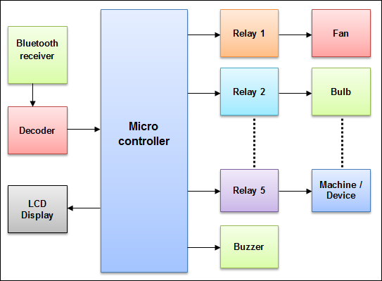
This project is one of the important Arduino Projects. Arduino based home automation using Bluetooth project helps the user to control any electronic device using Device Control app on their Android Smartphone. The android app sends commands to the controller — Arduino, through wireless communication, namely, Bluetooth. The Arduino is connected to the main PCB which has five relays as shown in the block diagram. These relays can be connected to different electronic devices like lights, television, fan, etc. Of technologies influence us to use smartphones to remotely control the home appliances.
Several remote controlled home automation systems have been studied. Arduino BT board was connected with home appliance and it was controlled by a Symbian OS cell phone application. Similarly, another study presented home automation system using Bluetooth and android application. However, this was designed only for 4 lights and it was not feasible to control more than 4 Home appliances. In another research work, XBee based home automation system introduced for handicapped and elderly people.
Configuration of Different Sensors
Multiple devices/appliances can be controlled using one Android device. And we need to connect bulb, fan, buzzer to these relays. Similarly, when the user presses on the ‘On’ button displayed on the app for the device 2, the fan is switched on. The fan can be switched off, by pressing the same button again. You can follow our last Gsm-based home automation project which helped many students to make their projects. If you have any queries in the post you can ask us in the comment section.
This Buzzer can be switched off, by pressing the same button again. After connected Bluetooth, your app screen will be like the above image now you can control the system, with the on and off button. Hey Guys, Welcome back to the Techatronic, we are Shahid and Adnan Electronics engineers making this awesome project for you. If you are looking for Home automation using Arduino and Bluetooth.
Share this document
To define connections, we use the following line of code. This line creates a LiquidCrystal object and lcd is a name of the object that we are going to use to call LCD functions. The pin configuration of the PIR sensor is shown in the figure. PIR sensor consists of three pins, ground, signal, and power at the side or bottom. Generally, the PIR sensor power is up to 5V, but, the large size PIR modules operate a relay instead of direct output. This is a home automation project in which we can control electrical appliances using smartphones via Bluetooth.
Now considering room scenario, an Arduino UNO will control devices and reads sensor data. The figure "Room Architecture" depicts how the Arduino UNO will connects with the devices and sensors. Room have multiple controllable devices(i.e. Light, Fan, Wall Socket, etc.), one PassiveIR , one temperature sensor and LDR .
Similarly, when the user says ‘2’ on the app, Device 2, i.e. the Buzzer is switched on. Whenever the user says ‘1’ on the app, Device 1, i.e. the Fan is switched on. 4) LCD Display – The Liquid Crystal Display is optional but shows important messages like device status once command is received from Bluetooth. Home automation and Device control can be done using the Internet of Things — IOT technology. In this research work two software Arduino Integrated Development Environment and Bluetooth terminal application are used.
XBee transceivers was used for wireless communication between the master control panel board and the remote control device. Nowadays, we have remote controls for our television sets and other electronic systems, which have made our lives really easy. If the answer is No, we have found a solution to it. We have come up with a new system called Arduino based home automation using Bluetooth. This system is super-cost effective and can give the user, the ability to control any electronic device without even spending on the remote control. This project helps the user to control all the electronic devices using his/her smartphone.
This voltage compared to the input voltage, that determines the desired position of the shaft, producing a voltage in the output of the comparator. This voltage powers the motor such that the shaft moves in the necessary direction to align with the angle that corresponds to the voltage applied to the input. For the sake of simplicity, we replaced the relay module made by us with the pre-built 4 channel relay in the final circuit diagram. 4 Channel Relay Board is a simple and convenient way to interface 4 relays for switching application in your project.
The HC-05 comes with multiple pins and indicators, which helps to control different operations and view their states through indicators. This pinout diagram provides indications of all pins. When the App successfully connects to the Bluetooth Module, Then you can see the blue light on the “Connection button“. At the same time, you can also see the LED on the Bluetooth Module is blinking with some delay.
Checking if the site connection is secure
After connected Bluetooth, your app screen will be like the above image now you can control the appliances with your smartphone. We can replace Bluetooth by GSM modem so that we can achieve device controlling by sending SMS using GSM modem. 6) Output devices – For the demo purpose, we connected 2 DC devices to 2 relays . You can connect any AC/DC devices to the remaining 3 relays. 1) A smartphone or an Android mobile which should have the android app installed in it. This project of home automation using Bluetooth and Arduino can be used for controlling any AC or DC devices.


No comments:
Post a Comment